NEWS
5G base station architecture and lifting antenna measurement technology
Time:2021-08-11 View:
5G base station architecture
To support multiple business applications such as enhanced mobile broadband (eMBB), ultra-high reliability and low latency (uRLLC), and large-scale machine communication (mMTC), 5G network will introduce NR New Air Port and new network architecture to improve network performance indicators such as peak rate, delay, and capacity, and have greater networking flexibility and scalability, to meet diverse business needs.
Currently, the 3GPP R15 standard has defined the overall architecture of 5G wireless networks. The 5G wireless access network (NG-RAN) consists of multiple 5G base stations (gNB). gNB provides UE with the termination of NR air interface protocol, and connects to 5G core network (5GC) network elements such as AMF/UPF through NG interface. gNB connects to each other through Xn interface.
Logical architecture of 5G base stations
5G base stations are mainly used to provide 5G air interface protocol functions and support communication with UE and core networks. According to logical functions, 5G base stations can be divided into 5G baseband units and 5G RF units, which can be connected through CPRI or eCPRI interfaces.
The 5G Baseband Unit is responsible for NR baseband protocol processing, including the entire user plane (UP) and control plane (CP) protocol processing functions, and provides the return interface (NG interface) with the core network. And inter-base station interconnection interface (Xn interface).
5G RF unit mainly completes the conversion of NR baseband signal and RF signal and the transceiver and processing function of NR RF signal. In the downstream direction, the baseband signal from the 5G Baseband Unit is received, processed by the up-conversion, digital-to-analog conversion, radio frequency modulation, filtering, signal amplification and other transmission links (TX), and then processed through the switch, the antenna unit is transmitted out. In the uplink direction, the 5G RF unit receives the uplink RF signal through the antenna unit. After receiving link (RX) processing such as low-noise output, filtering, and demodulation, the 5G RF unit performs analog-to-digital conversion and downconversion, convert to baseband signal and send to 5G Baseband Unit.
5G base station equipment system
From the perspective of device architecture, 5G base stations can be divided into different architectures such as BBU-AAU, CU-DU-AAU, BBU-RRU-Antenna, CU-DU-RRU- Antenna, and integrated gNB. In the BBU-AAU architecture, the baseband unit is mapped to a separate physical device BBU. The AAU integrates the RF unit and the antenna unit. If the eCPRI interface is used, the AAU also contains some underlying physical layer processing functions. In CU-DU-AAU architecture, the baseband functions are distributed to two physical devices, CU and DU, which together form a 5G Baseband Unit. The F1 interface between CU and DU is a medium transmission interface. In the BBURRU-Antenna architecture, RRU has the same function as AAU. The difference is that RRU does not have a built-in antenna unit and requires an external antenna. It is mainly used in low-capacity scenarios such as suburban areas or indoor coverage scenarios. The integrated gNB Framework integrates 5G Baseband Unit, RF unit and antenna unit. It is a highly integrated and compact device and can be used in special scenarios such as local area blind compensation or indoor coverage.
From the perspective of equipment form, 5G base stations can be divided into baseband equipment, RF equipment, integrated gNB equipment and other forms of equipment. Among them, 5G baseband equipment also includes different types of physical equipment of BBU, CU and DU, while 5G RF equipment includes AAU and RRU equipment.
Antenna measurement technology
Most LTE 4G antennas are passive antenna arrays, and RF analog phase shifting is often used to adjust the antenna downtilt angle. The 5G MassiveMIMO antenna is an active antenna integrated with the transceiver channel and antenna array, and the amplitude and phase distribution of the antenna unit is completed by the digital baseband part. The test methods and indicators of the original passive antenna cannot meet the requirements of 5G antenna. 5G antenna should introduce some new test indexes to reflect the design advantages and disadvantages of active antenna system.
Passive test Index
The measurement of antenna passive parameters such as gain and pattern can still be tested by the previous test method.
Active downlink indicator
Equivalent omnidirectional radiation Power (Effective Isotropic Radiated Power, EIRP) is the product of the Power supplied by the radio transmitter to the antenna and the absolute gain of the antenna in a given direction. An ideal omnidirectional antenna with the same unit gain in all directions is usually used as a reference antenna for wireless communication systems.
Active uplink indicator
Equivalent omnidirectional sensitivity (EIS): When the signal comes from a certain direction, the receiver can satisfy the normal electromagnetic wave power density multiplied by the spherical area; For the antenna with gain G, EIS equals the sensitivity when receiving an amplifier with a gain of G with an ideal omnidirectional antenna.
In-band blocking indicator
Adjacent Channel Selectivity (Adjacent Channel Selectivity,ACS): Considering the receiver's receiving capability when there are large interference signals in the receiving frequency band. This index is mainly guaranteed by uplink channel shaping filter, receiving Channel gain linear range and AGC function.
Co-location test
At present, in order to reduce operating costs, many base stations of different systems adopt co-site construction, that is, base stations of different systems adopt common celestial surface or even shared pole. The purpose of the co-location test is to judge the degree of mutual interference between the base station antennas of different systems when they share the sky surface or even the pole, mainly testing the blocking interference and stray interference. Blocking interference means that when the system receives signals, it is subject to strong interference signals from other systems near the receiving frequency band and in the high frequency loop band, which is beyond the linear range of the receiver, resulting in the receiver being unable to work due to saturation; stray interference means that due to the unsatisfactory filtering characteristics of interference sources (other systems), out-of-band signals of interference sources appear in adjacent frequency bands of the system in the form of noise, the base noise of the base station of the system rises, the receiver desensitization, and the uplink performance deteriorates.
OTA test field analysis
the station types of 1-H,1-O and 2-O defined in the 5G standard all stipulate corresponding OTA(over the air) RF test items. Especially for the station type of 1-O and 2-O, without the antenna interface of traditional conduction test, all RF test items need to be tested in OTA environment, and the test items include transmitting power, modulation quality, occupied bandwidth, adjacent channel leakage power ratio, spurious, Intermodulation, sensitivity, blocking, etc. Therefore, the whole radio anechoic chamber used for OTA testing, such as Far Field, contraction field, midfield, small field with plane wave generator, etc., becomes a necessary environmental choice. 3GPP standard suggests four options: Far Field, compression field, one-dimensional compression field and near field, and gives calibration and test method suggestions for MU(Measurement Uncertainty) and related test items of different fields. For one-dimensional compression field, existing institutions have developed plane wave generator according to similar principles, and have also conducted a lot of system testing and verification work.
CATEGORY
NEWS
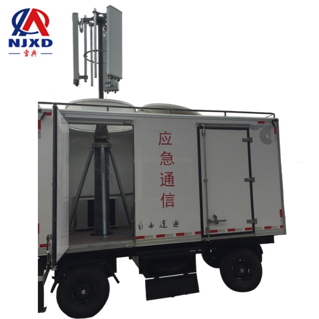
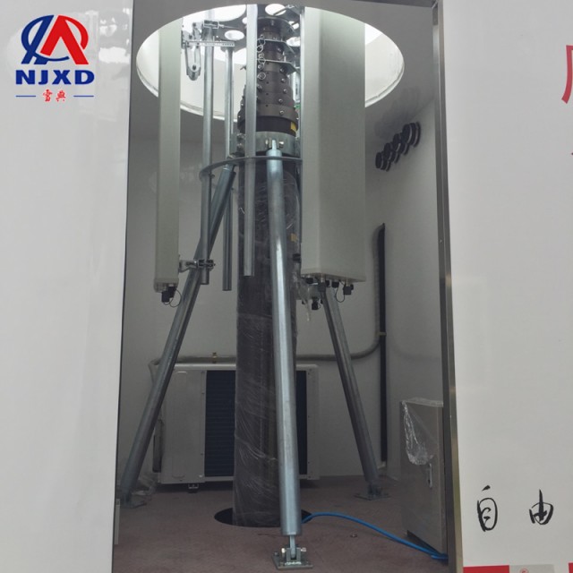
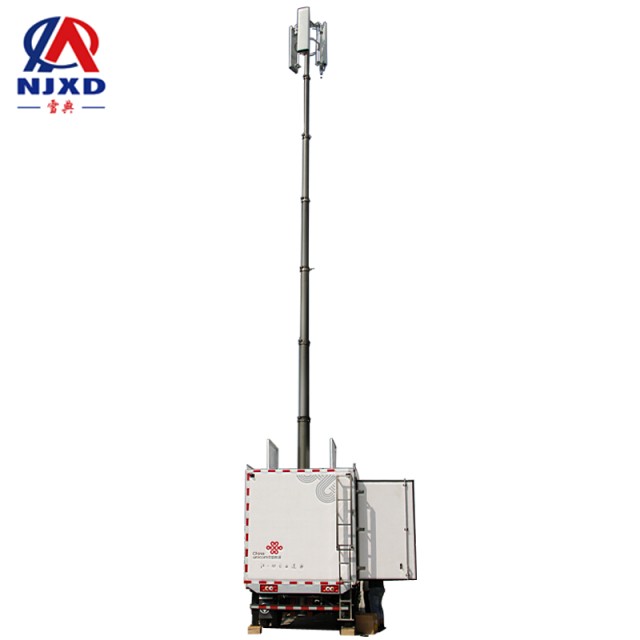
- Working Principle and composition of emergency communication base station
- 5G base station architecture and lifting antenna measurement technology
- Xenon lamp quality test lighting telescopic rod
- Outdoor Base Station wireless survey and design base station lifting antenna
- Lift Rod classification and application characteristics of packing wooden cases