NEWS
Lift rod bending moment
Time:2021-04-21 View:
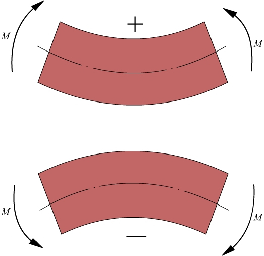
Bending moment is a kind of internal moment on the cross section of stressed components. Popular saying: bending moment is a kind of moment. Another explanation is that the moment required for bending is that the lower tension is positive (upper compression) and the upper tension is negative (lower compression). Its standard definition is: the combination of the distributed internal force system perpendicular to the cross section moment of couple.
Calculation Formula M = θ · EI/L,θ angle, EI rotational stiffness, effective calculation length of L rod.
Definition and content
Bending moment is a kind of internal moment on the cross section of stressed components, that is, the combination of internal force system perpendicular to the cross section moment of couple. Its size is the algebraic sum of all external forces on the component part of the cross section to the centroid moment of the cross section, and its positive and negative is set to be that the component concave downward is positive, the upper convex is negative (positive and negative distinguishing criteria are that the upper compression of the component is positive and the lower compression is negative; Otherwise, the upper tension of the component is negative and the lower tension is positive. In civil engineering, the bending moment diagram is used to be drawn on the tensile side of the bar, and plus or minus is not indicated on the diagram). For example, for a cantilever beam, when the beam end force is 2kN, the beam length is 3m, the rigid end bending moment is-6kN · m, and the cross-Middle bending moment of the beam is-3kN · m, according to this method, it can be calculated simply, but the deeper algorithm needs to see mechanics of materials.
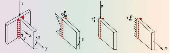
In Figure 3, ↓,M is the bending moment, v is the shearing force, and n is the axial force.
Distinguish positive and negative
Generally speaking, the positive bending moment has different regulations in different disciplines. If the positive and negative bending moment is specified, the bending moment can be calculated algebraic.
When calculating the column bending moment, the discrimination method of "top left, bottom right, bottom left and top right are positive, bottom left and top right are negative" is applied. Where the moment of external force on the left side beam of the cross section turns clockwise to the moment of the cross section centroid, or the moment of external force on the right side of the cross section turns counterclockwise to the moment of the cross section centroid, positive bending moment will be generated, so positive sign will be taken; on the contrary, it is negative, that is, left, right and reverse, and the bending moment is positive.
For a beam in the civil engineering structure (refers to the horizontal component), when the lower side of the component section is under tension, we call the bending moment of this section as a positive bending moment; when the upper side of the component section is pulled, we call the bending moment of this section negative bending moment.
The bending moment direction given by PKPM:
Force direction (for Foundation): axial force N pressure is positive (↓);
The bending moment M is positive clockwise (-↓);
Shear V is positive clockwise (→).

Calculation formula
Bending moment formula:
Mmax = FL/2 (Mmax indicates the maximum bending moment, F indicates the external force, and L is actuating arm).
Bending moment diagram
Bending moment diagram is a kind of graph line, which is used to indicate the change of bending moment along the axis of each cross section of a beam. The summary rules are as follows:
(1) in a certain section of the beam, if there is no distributed load, that is, q(x)= 0, from d² M(x)/dx ² = q(x)= 0, it can be seen that M(x) is a function of x, and the bending moment diagram is an oblique straight line.
(2) in a certain section of the beam, if the effect is distributed load, that is, q(x)= constant, then d² M(x)/dx ² = q(x)= constant, you can get the quadratic function that M(x) is x. The bending moment diagram is a parabola.
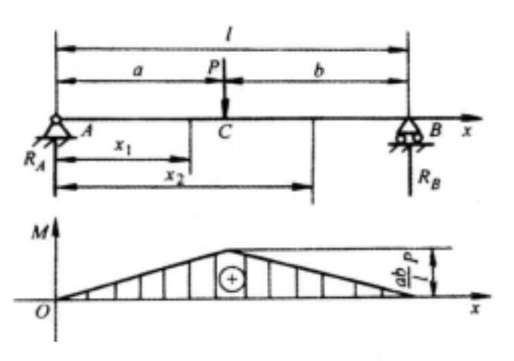
(3) in a certain section of the beam, if Fs(x)= dM(x)/dx = 0, the bending moment on this section has an extreme value (maximum or minimum). That is, the extreme value of bending moment occurs on the section with zero shear force.
Superposition principle
Figure 6-9 a, B and c respectively show the three kinds of stress situations of the same matte AB under the action of q, M0, q alone and M0 alone.
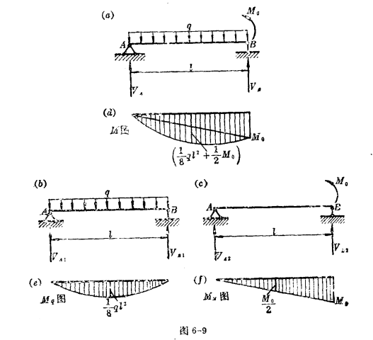
When q and M0 work together
VA=ql/2+M0/l VS=ql/2+M0/l
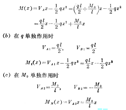
From the calculation results, we can see that the bearing reaction force and bending moment of the beam are all functions of the load (q, M0), that is, the reaction force or bending moment has a linear relationship with the load. At this time, the reaction force or bending moment generated by g and M0 acting together F is equal to the algebraic sum of the reaction force or bending moment generated by g and M0 acting alone:

This relationship exists not only in this example, but also in other mechanical calculations, that is, as long as the reaction force, bending moment (or other quantities) have a linear relationship with the load, then the reaction force, bending moment (or other quantities) caused by several loads are equal to the superposition of reaction force, bending moment (or other quantities) caused by each load alone. This relationship is called superposition principle. The premise of applying superposition principle is that the component is under the condition of small deformation, and then the influence of each load on the component is independent.