NEWS
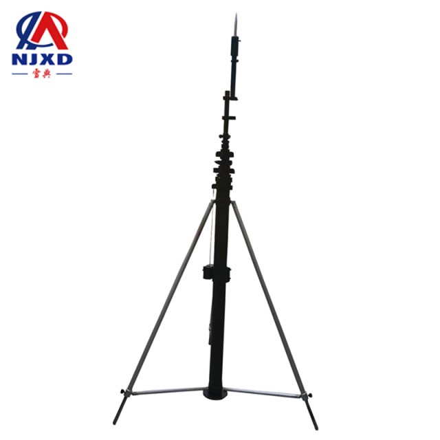
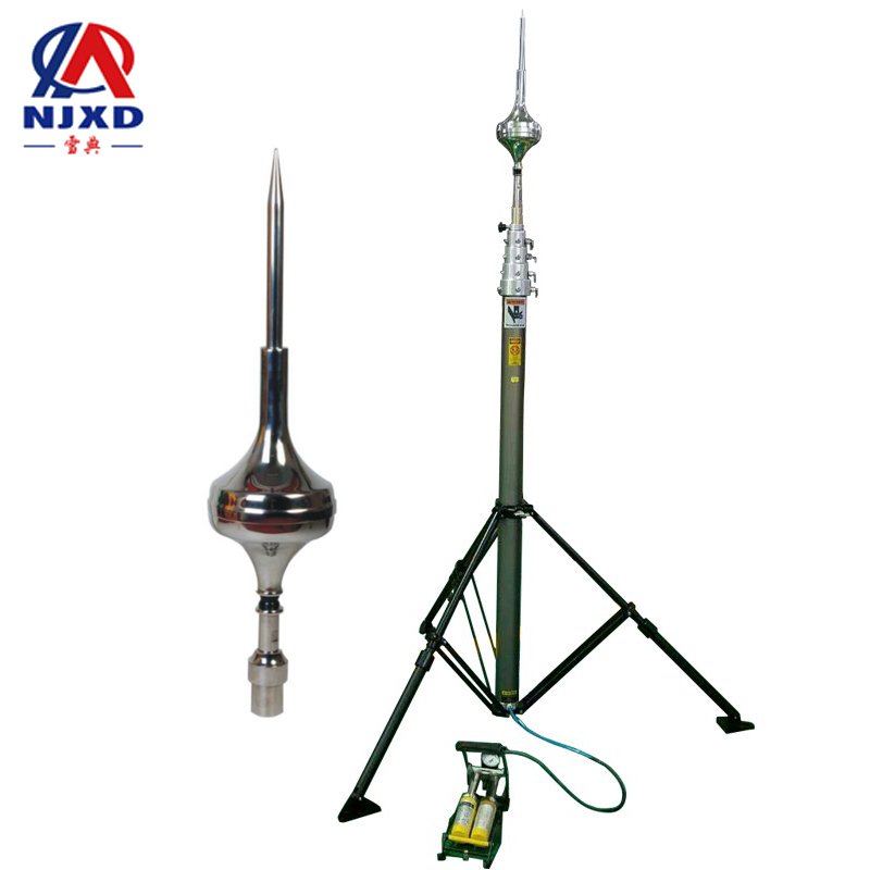
Installation of grounding device ightning Rod telescopic rod
Time:2021-05-10 View:
Installation
(1) General requirements
First of all, make full use of the natural grounding body to save investment. If the resistance of the natural grounding body measured on the spot has met the requirements of the grounding resistance value and the condition of thermal stability, there is no need to install artificial grounding device, otherwise, artificial grounding device should be installed as supplement.
The arrangement of artificial grounding device should make the potential distribution near the grounding device as uniform as possible to reduce the contact voltage and step voltage and ensure personal safety.
(2) utilization of natural grounding body
Steel structures and steel bars of buildings, rails of traveling vehicles and buried metal pipelines (except combustible liquid and combustible explosive gas pipelines) as well as the metal outer skin of cables laid underground with no less than two cables, etc., can be used as natural grounding bodies. The power transformation and distribution office can use its building reinforced concrete foundation as a natural grounding body. When using the natural grounding body, make sure that the electrical connection is good.
(3) installation of artificial grounding body
Artificial grounding body has two basic structural types: vertical embedding and horizontal embedding.
The commonly used vertical grounding body is a steel pipe with a diameter of 50mm and a length of 2.5m or an angle steel with a length of L50 × 5. In order to reduce the influence of external temperature changes on convection diffusion resistance, the upper end of the vertical grounding body buried underground should not be less than 0.7m from the ground.
For grounding devices laid in places with strong corrosion, anti-corrosion measures such as hot tin plating and hot galvanizing should be adopted according to the corrosion properties, or the cross section should be appropriately enlarged.
When multiple grounding bodies are close to each other, the current flowing into the ground is squeezed out each other, and this effect is called shielding effect. This reduces the utilization rate of grounding device, so the distance between vertical grounding bodies should not be less than 5m, and the distance between horizontal grounding bodies should not be less than 5m.
For the arrangement of ground grid, the potential distribution on the ground should be as uniform as possible to reduce the contact voltage and step voltage. The outer edge of the artificial ground grid should be closed, and the outer edge should be made into circular arc. Horizontal voltage sharing belts shall be laid in the grounding grid of 35~110kV/6 ~ 10kV substation. In order to reduce the contact voltage of the building, the horizontal distance between the grounding body and the foundation of the building should be kept at least 1.5m, generally 2~3m.
Equipotential connection
Equipotential connection is a measure that does not need to add protective electrical appliances. As long as some connecting wires are added, the potential can be equalized and the contact voltage can be reduced, thus eliminating the danger of electric shock caused by potential difference. It is economical and can effectively prevent electric shock.
Equipotential connection usually includes total equipotential connection and auxiliary equipotential connection. The so-called total equipotential connection is to connect the PE wire or PEN wire of the electrical device with all nearby metal pipe components (such as grounding trunk lines, water pipes, gas pipe, heating and air conditioning pipes, etc, if possible, it also includes steel bars and metal components of the building) and equipotential connection terminal board (I .e. ground terminal board) at the entrance to the building. The total equipotential connection reduces the contact voltage by equalizing the potential and eliminates the dangerous voltage introduced into the building from the power supply line.
The main purpose of the total equipotential connection is not to shorten the action time of the protective appliance, but to make the potential between the exposed conductive part and the external conductive part that people can touch at the same time approximately equal, the contact voltage will drop below the safety value. Under normal conditions, safe potential is 50V and 25V in humid environment. When automatic power cut-off is adopted as a measure to prevent indirect electric shock, total equipotential connection is indispensable.
Auxiliary equipotential connection is also called local equipotential connection, which connects PE wire or PEN lines with all nearby exposed conductive parts and external conductive parts within a local range, make it at the same potential in the local range as a supplement to the total equipotential connection. The main purpose of local equipotential connection is to reduce the contact voltage below safe potential.
Buildings equipped with lightning protection devices should also adopt equipotential connection when lightning protection devices cannot be isolated from other facilities and personnel in the buildings.
When some electrical devices are located outside the total equipotential connection active region, leakage circuit breaker should be installed, and the PE wire of this part should be isolated from the PE wire of the power supply incoming line and connected to a separate grounding electrode, prevent dangerous voltage from entering outside.

Quality Standard
GB50169-92 grounding device construction and acceptance specification?
1. The top laying depth of grounding body shall meet the design requirements. When it is irregular, it should not be less than 0.6m. Angle steel and steel pipe grounding body should be vertically configured. In addition to the grounding body, the vertical part of the grounding body outlet line and the welding part of the grounding device should be treated with anti-corrosion; Before the anti-corrosion treatment, the surface must be derusted and the residual solder medicine in the welding place must be removed.??
2. The distance between vertical grounding bodies should not be less than 2 times of their length. The distance between horizontal grounding bodies shall conform to the design regulations. When there is no design regulation, it should not be less than 5m.??
3. The grounding wire should prevent mechanical damage and chemical corrosion; The grounding wire should be equipped with steel pipes or other solid protective tube at the place passing through walls, floors and floors, anti-corrosion measures should also be taken for parts with chemical corrosion.??
4. The grounding trunk line should be connected to ground grid at different two points or more.??
5. The grounding of each electrical device should be connected with the grounding trunk line by a separate grounding wire, and several electrical devices that need grounding should not be connected in series in one grounding wire.??
6. Stone and construction waste should not be included in the backfilling soil of the earth trench after the grounding body is laid; Get from the outside of the soil should not be highly corrosive; It should be implemented in layers when backfilling the soil.??
7. The connection of grounding body (line) should be welded, and the welding must be firm without virtual welding. Connect to the grounding wire of electrical equipment and connect it with galvanized bolts.??
8. The welding of grounding body (line) should adopt lap welding, and its lap length must meet the following regulations:??
(1) flat steel is twice its width (and at least 3 edges are welded).??
(2) round steel is 6 times of its diameter.

CATEGORY
NEWS
- Grounding device classification ightning rod lift rod
- Installation of grounding device ightning Rod telescopic rod
- Lightning protection device introduction ightning Rod lifting bracket
- Components of lightning protection device ightning Rod telescopic mast
- Classification of grounding method ightning Rod lifting mast