NEWS
Principle of lifting ightning rod bracket
Time:2021-05-21 View:
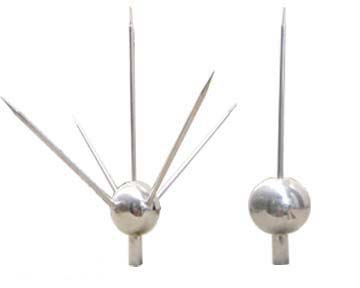
In thunderstorm weather, when there are charged clouds over high-rise buildings, lightning Rod and the top of high-rise buildings are induced with a large amount of charge. Because ightning Rod needles are sharp, when static electricity is induced, the tip of the conductor always gathers the most charge. In this way, ightning rod collects most of the charge. Ightning Rod forms a capacitor with these charged clouds, because it is relatively sharp, that is, the positive opposite area of the two poles of this capacitor is very small, that is to say, it can hold very little charge. However, it collects most of the charges, so when there are more charges on the clouds, the air between the ightning Rod and the clouds is easily broken down and becomes a conductor. In this way, charged clouds form a path with ightning rod, and the ightning rod is grounded. Ightning Rod can introduce the charge on the clouds into the Earth, making it not dangerous to high-rise buildings and ensuring its safety.
The lightning protection function of ightning rod is that it can lead Lightning to itself from above preserver and safely leak it into the earth through itself. Therefore, its lightning induced performance and discharge performance are crucial. The experimental and theoretical analysis of the lightning-induced performance of ightning rod is as follows:
A mine-induced airspace of a ightning Rod erected on the flat ground is shown in Figure 1. The simplified envelope is a parabola, which is the 50% average boundary of the ightning rod hit point under positive and negative thunderstorm clouds. In the figure, small circle shows the discharge statistics of experiments at various points in the air, indicating the position of the needle tip of the pilot in the simulation experiment. The black circle indicates 100% hitting the needle, and the white circle indicates 100% hitting the ground, half of the black and white indicates 50% of the hit needle and hit the ground.
The discharge intensity of lightning strike ightning Rod and the ground is related to the polarity of the lightning electrode: When the polarity of the Thunder is positive, the discharge intensity of the Thunder to ightning rod is higher than that of the Thunder to the ground; When the polarity of the Thunder is negative, the discharge intensity of Lei to ightning rod is slightly lower than that of Lei to the ground. Therefore, under the same voltage, the discharge distance R of the lightning electrode to the needle is different from the discharge distance H of the lightning electrode to the ground. According to the experimental data of long gap discharge, there are roughly:
Lightning is extremely negative, ground is positive, k = R/H = 1.1
When lightning is extremely positive and ground is negative, k = R/H = 0.8~0.9,
Figure 2 is the theoretical analysis diagram of the ground boundary surface of the lightning strike needle, according to which the theoretical boundary line between the ightning rod of the lightning strike and the ground can be obtained.
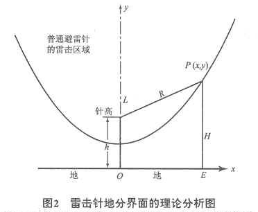
In the figure, L is ightning rod tip, its height is h,P is the head of the Thunder electrode, its height to the ground is H,E is the projection point directly below the Thunder electrode, L, the distance between P is R. When point p maintains k equal to a constant moving on the surface, its motion trajectory is the theoretical dividing line between lightning strike ightning Rod and ground. The rotation of the dividing line centered on the y axis is the three-dimensional interphase. Within interphase is the airspace of lightning strike ightning Rod, outside interphase is the airspace of lightning strike land, and the lightning strike ground near interphase is the scattered strike area.
There are three kinds of dividing lines: When k = 0.9, its dividing line is ellipse; When k = 1.1, its dividing line is hyperbolic; When k = 1, its dividing line is parabolic, the latter is the theoretical basis for general analysis of ightning Rod Lightning connection performance, which is the average of positive and negative lightning strikes. The analysis results of figure 2 are consistent with the experimental results of figure 1.
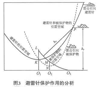
Based on the analysis of the protection scope of ightning rod in the mine-induced airspace of ightning Rod, the protection effect can be ightning Rod when k = 1 is taken, as shown in figure 3.
In Figure 3, O1 L is ightning Rod, K is the mid-point of its height; MO2 is Preserver, and N is the mid-point of its height. Assuming that the lightning strike distance is hr, the Lightning pilot terminal is located at P,PK (solid line) is the lightning strike boundary line of ightning rod, and PN (dotted line) is the lightning strike boundary line of preserver, its upper airspace is within ightning rod of the lightning diversion boundary. Therefore, lightning strikes with a height greater than hr from the ground will be led to ightning rod, and preserver MO2 will be protected from lightning strikes. This phenomenon is called intercept effect; However, when the Lightning pilot strikes from the right side lower than hr, ightning rod will not play a protective role, which is called side attack on the preserver. Therefore, with point p as the center of the circle and hr as the radius as the circle, this circle passes through point O3 on the ground M from vertex L of ightning Rod, and the following part is the protection range of ightning Rod when the lightning strike distance is hr. This analysis result is consistent with the results obtained by the grounder method of electrical geometry theory (EGM).
EGM theory holds that the lightning pilot first enters the lightning distance of which object is discharged to that object, and the Lightning distance is a function of lightning current:
hr=10I0.65 (1)
In the formula, hr is lightning strike distance, m;I is lightning current amplitude, kA.
U.S. R.H.Lee suggests taking 10 kA as the critical current Ic of general buildings, which will not cause lightning strike accidents when it is less than this lightning current amplitude, and its corresponding critical lightning strike radius hrc is 45 m. This view links the lightning resistance level of preserver with the protection rate of ightning rod. China's lightning protection standard GB50057-94 "design code for lightning protection of buildings" stipulates that the scope of lightning conductor protection of three types of lightning protection buildings is drawn according to the hrc of 60 m. Operation experience shows that this regulation meets the lightning protection requirements of general buildings in our country.
Some scholars have revised EGM theory, which is called pilot propagation model theory (LPM). This theory holds that to determine the lightning strike point, besides considering the lightning strike distance, the relative motion of the head-on pilot and the downward pilot should be considered. Whether the ground objects with a certain geometry and height can be hit by lightning with a certain lightning current amplitude can be expressed by the attraction radius Ra. Ra is not only a function of lightning current, but also a function of the height of ground objects, and is related to the geometry of ground objects. Because ground objects of different shapes and heights have different electric field intensity induced under the downward leading action of the same lightning current.
Ra( I ,h)=2.83I0.63h0.40 (2)
In the formula, Ra is attraction radius, m;I is lightning current amplitude, kA;h is needle height, m.
The analysis results show that when the critical radius hrc is greater than ightning rod height h, the protection radius obtained by EGM is smaller than LPM, but it is not significant; When the critical radius hrc is smaller than the needle height h, the protection radius obtained by EGM is much smaller than that of LPM, which is about 50% smaller in some cases. When the needle height H> hrc, EGM thinks that the needle body part higher than the critical radius has no protection range, however, LPM theory holds that the protection radius varies with the needle body.
The height increases.
According to the observation that the number of lightning strikes attracted by tower-shaped buildings changes with the increase of their height and the experimental results of long-gap discharge rods on rods, it is proved that the lightning-induced capacity of ightning Rod increases with the increase of their height, but increment speed is slow. This supports the conclusion of LPM. It can be seen that EGM grounder method does not consider the change of attraction power with height, which is the reason why its protection range is too small. From a theoretical point of view, grounder is a conservative and strict method, which can give intuitive physical images to ightning rod protected areas.
Considering the relative motion of the head-on pilot and the downward pilot, we can get ightning rod of the Thunder-induced airspace, as shown in figure 4.
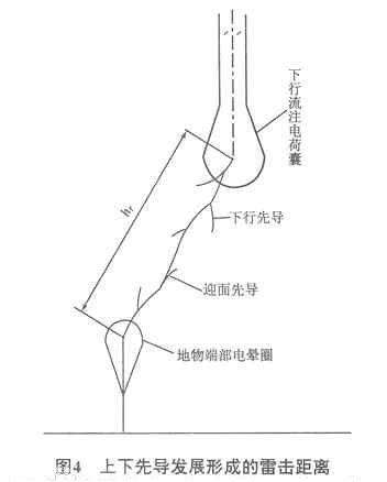
Figure
hr=vzhT+vxiaT (3)
In the formula, hr is the lightning strike distance, that is, the lightning strike radius, m;vzh is the development speed of ground objects or ightning Rod head-on pilot, m/s;vxia is the development speed of ground flash downward pilot, m/s;T is the discharge delay of the atmospheric gap, s.
All conclusions of LPM theory can be obtained by referring to Fig. 3.
The upper part of ightning Rod has a space where it may suffer lateral lightning strike, which is called the side strike area of the needle bar; The elevated ightning Rod has a strong lightning guiding ability, when the downward lightning pilot coming from the side is brought closer by ightning Rod and fails to flash at the pin end, lightning strikes will occur.
The situation of the ground near ightning Rod makes the density of the ground falling Thunder near the elevated ightning Rod higher than the average density of the ground falling Thunder, which is called the scattered strike area. High buildings and elevated ightning Rod appear scattered hit areas near the ground, and the lightning strike rate far away from ightning rod is not affected by ightning rod, which is called normal area. Ightning Rod see figure 5 for the lateral attack area of the surrounding space, the protection area of the ground, the scattered attack area of the ground and the normal area.
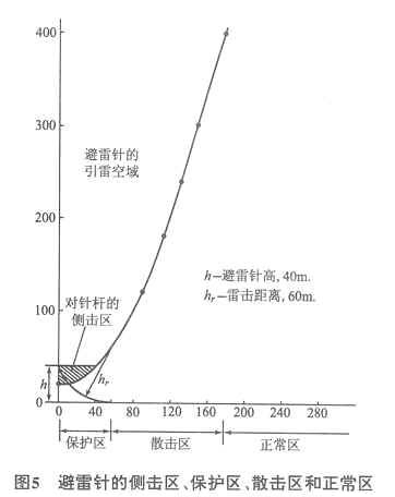
According to the statistics of our country, the maximum lightning current amplitude is about 300 kA, and the corresponding lightning strike height is 408 m. Taking the lightning strike positioning height of 400m, the surface radius of protected areas and scattered strike areas with different heights of ightning rod can be obtained as shown in Table 1. The height of old houses in our country is generally below 10 m, the height of lightning strip and lightning conduction is the same as that of houses, and the height of short needle lightning protection installed is 1~2 m, the phenomenon of scattered strike caused by them is not obvious; High-rise buildings and elevated ightning Rod lead to higher lightning strike rate and existing scattered strike areas. Chinese lightning protection scholars have always not advocated the use of elevated lightning conductor protection buildings, and the use of short roof pins and lightning protection belts is considered to not only play its role in triggering Thunder, but also to avoid increasing mine scattering areas.
Scope of protection
1 piece of ightning Rod protection range
When the height of ightning Rod h ≤ hr
From the ground hr, make A parallel wire parallel to the ground, take the needle tip of ightning Rod as the center of the circle, hr as the radius to draw an arc, cross the horizontal line at two points A and B, and take A, B two points are the center of the circle, hr is the radius, and arc is drawn from the tip of the needle to the ground. As shown in Figure 1, the curve in the figure is the boundary of the lightning conductor protection range, and the protection range is a symmetrical cone.
Value of Hr
A class of lightning protection buildings is 30 meters
Class II lightning protection building is 45 meters
Three types of lightning protection buildings are 60 meters
Joint grounding
With the maturity of lightning protection and grounding technology, people gradually realize that lightning protection and grounding are a systematic project and put forward the concept of joint grounding (as shown in the figure).
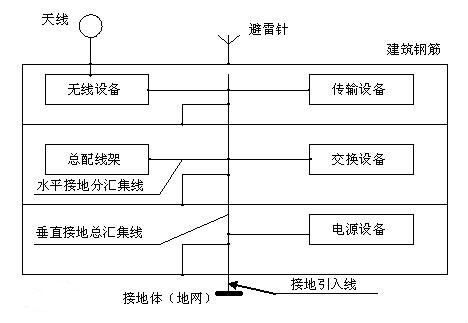
People weld all the steel bars around the building into cages, and use the structure of the peripheral steel bars of the building as the down lead of lightning. The steel bars of the building are reliably connected to the Earth through ground grid at the Foundation, lightning is introduced through ightning Rod (lightning belt, Lightning conduction) and enters the ground through the steel bars outside the building, thus effectively protecting the interior of the building. The effect is better than that of lightning down lead alone.