NEWS
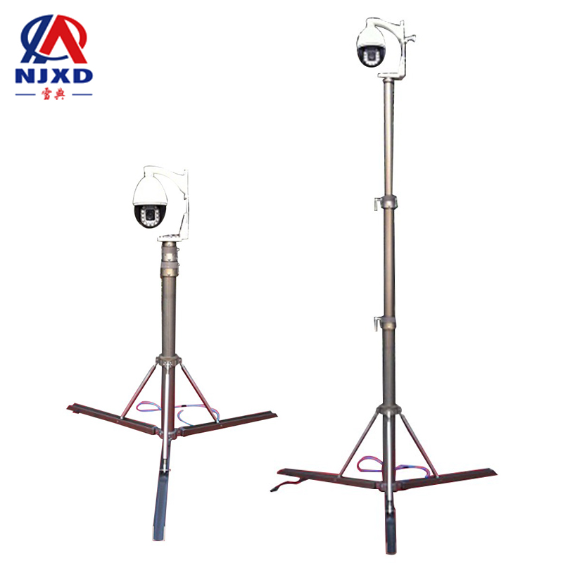
Common faults of lifting security monitoring
Time:2021-06-17 View:
Troubleshooting
After a security monitoring system enters the debugging stage, trial operation stage and is delivered for use, such failures may occur, such as: failure of normal operation, failure of the system to meet the technical indicators required by the design, the overall performance and quality are not ideal, that is, some "soft problems". These problems are inevitable for a monitoring system project, especially for a complex and large-scale monitoring project.
Incorrect power supply
Incorrect power supply has the following possibilities: Incorrect power supply line or voltage, insufficient power (or insufficient wire diameter of one power supply line, excessive voltage reduction, etc.), the transmission line of the power supply system has short circuit, open circuit, instantaneous overvoltage, etc. Especially when the equipment is damaged due to wrong power supply or instantaneous overvoltage. Therefore, in the system debugging, before power supply, we must check and check carefully and strictly, and never take it lightly.
Poor wiring
. Because some devices (such as cameras with Sanke variable lens and PTZ) have many links, if they are not handled well, especially the lines connected with the devices are not handled well, open circuit, short circuit, poor insulation between wires, miswiring and other problems that lead to equipment damage and performance degradation. In this case, the fault phenomenon should be analyzed calmly according to the fault phenomenon, and the fault phenomenon should be determined because of the connection problems of several lines. This will narrow down the scope of problems. It is particularly worth pointing out that due to the all-round movement of the camera with pan-tilt, it is common for the camera to fall off and break off the wiring for a long time. Therefore, special attention should be paid to the connection between the equipment and various lines in this case should meet the requirements of long-term operation.
Quality problem
Theoretically, quality problems may occur in all kinds of equipment and components. However, from experience, it is purely a quality problem of the product itself, which mostly occurs in Decoder, professional electrical platform, transmission components and other equipment. It is worth pointing out that the quality of some equipment may not be unusable as a whole, but it cannot reach the indicators given in the product specification from some technical indicators. Therefore, necessary sampling inspection must be carried out for the selected products. If it is indeed a product quality problem, the best way is to replace the product instead of dismantling and repairing it by yourself.
In addition, the most common problem is caused by improper adjustment of equipment. For example, the adjustment of the rear intercept of the camera is a very detailed and accurate work. If it is not carefully adjusted, problems such as poor focusing or defocus occur during various operations of Sanke variable lens will occur. In addition, whether the positions of some switches and adjustment knobs on the camera are correct, whether they meet the technical requirements of the system, whether the decoder encoding switch or other adjustable parts are set correctly or not will directly affect the normal use of the equipment itself or the normal performance of the whole system.
Incorrect connection
Problems caused by incorrect connection between equipment (or components) and equipment (or components) generally occur in the following aspects:
(1) impedance mismatch.
(2) the communication interface or communication mode does not correspond. This situation mostly occurs between the control host and devices with communication control relationship such as decoders or control keyboards, that is to say, the selected control host and decoder or control keyboard are not caused by the products of the same manufacturer. Therefore, the products of the same manufacturer should be selected for the host, decoder, control keyboard, etc.
(3) the drive capability is insufficient or exceeds the specified number of device connections. For example, some images splitter have alarm input interfaces. In their product specifications, system hosts connected with alarm probes and long-delay video recorders are connected into systems, if the alarm probe is connected to the alarm input of the screen splitter again, the alarm signal of the probe will not only drive the alarm host, but also drive the screen splitter. In this case, the problem of insufficient driving capability often occurs. The phenomenon is that although the picture splitter can alarm, it is unstable because the input alarm signal is weak, as a result, the image of the camera corresponding to the alarm signal is instantly converted into a full-screen image on the monitor, but it is lost (can't be kept), however, the images on the monitor are still multiple images before the alarm.
One way to solve the above problems is to connect the alarm probe signal to the screen splitter or video switching host through a dedicated alarm interface box. Second, when there is no alarm interface box, you can design signal expansion equipment or driving equipment by yourself.
Video failure
The problems mentioned above sometimes occur in the output and distribution of video signals.
Horizontal bar interference
In video transmission, the most common failure phenomenon is that a black bars or white bar appears on the monitor screen and slowly scrolls up or down. Therefore, when analyzing this kind of failure phenomenon, two different causes of the failure should be distinguished. To distinguish whether it is the problem of power supply or the problem of ground loop, a simple method is to connect only one camera with no problem of power supply nearby to the control host to output signals, if the above interference does not occur on the monitor, there is no problem with the control host. Next, a portable monitor can be connected to the video output of the front-end camera and each camera can be checked one by one. If yes, process. If not, the interference is caused by other reasons such as the ground loop.
Wood grain interference
Wood grain interference appears on the monitor. The appearance of this kind of interference will not submerge the normal image when it is slight, while the image cannot be viewed when it is serious (even destroying synchronization). The causes of this failure phenomenon are many and complicated. There are several reasons:
(1) the quality of the video transmission line is not good, especially the shielding performance is poor (shielding net is not a copper wire network with good quality, or shielding net is too thin to shield). At the same time, the line resistance of this kind of video cable is too large, thus causing large signal attenuation is also the cause of the fault. In addition, the characteristic impedance of this kind of video cable is not 75Ω and the parameter exceeds the regulation, which is also one of the causes of failure. Because the above interference phenomenon is not necessarily a fault caused by bad video cable, the cause of this fault should be accurate and cautious when judging. Only when other possibilities are excluded can we consider them from the perspective of bad video cable. If it is really a cable quality problem, of course, the best way is to replace all such cables with cables that meet the requirements, which is the best way to completely solve the problem.
(2) caused by the power supply of the power supply system is not "clean. The power supply referred to here is not "clean", which means that interference signals are superimposed on the normal power supply (50-week sine wave). And this kind of interference signal on the power supply mostly comes from the equipment using silicon controlled rectifier in the power grid. Especially the silicon controlled devices with large current and high voltage have very serious pollution to the power grid, which leads to the power supply in the same power grid is not "clean". For example, the power grid has high-power thyristor frequency modulation speed control device, Thyristor rectifier device, thyristor AC/DC converter device, etc., which will cause pollution to the power supply. The solution to this situation is relatively simple. As long as the whole system is powered by purified power or online UPS, it can basically be solved.
(3) There are strong interference sources near the system. This can be judged through investigation and understanding. If this is the reason, the solution is to strengthen the shielding of the camera and carry out grounding treatment on the pipeline of the video cable.
Mesh interference
Faults caused by short circuit and open circuit between the core wire of the video cable and shielding net. The manifestation of this kind of fault is to generate deep and chaotic large-area mesh interference on the monitor, so that all the images are destroyed and the images and synchronization signals are not formed. This situation occurs on BNC (bayonet nut connector) or other types of video connectors. That is to say, when this kind of failure phenomenon occurs, it is often not that all signals of the whole system have problems, but only in the number of bad joints. As long as you carefully check these joints one by one, you can solve it.
Vertical bar interference
Fault phenomenon caused by mismatch of characteristic impedance of transmission line. The manifestation of this phenomenon is to generate several vertical bar interference with equal spacing on the monitor screen, and the frequency of the interference signal is basically an integer multiple of the line frequency. This is due to the characteristic resistance of video transmission line
Resistance is not caused by impedance mismatch caused by 75Ω. It can also be said that this kind of interference phenomenon is caused by the combination of the characteristic impedance and distribution parameters of the video cable that do not meet the requirements. The solution generally depends on the method of "connecting resistance at the beginning and end" or "connecting resistance at the terminal. In addition, it is worth noting that when the video transmission distance is very short (generally within 150 meters), the above-mentioned interference phenomenon may not occur in video cables using the above-mentioned impedance mismatch and excessive distribution parameters. The fundamental way to solve the above problems is to ensure the quality when purchasing video cables. If necessary, the cable shall be sampled.
Other interference
Space radiation interference introduced by transmission line. Most of the interference phenomena are caused by strong and high frequency space radiation sources near the transmission system, the front end of the system or the central control room. One solution to this situation is to understand the surrounding environment when the system is established and try to avoid or stay away from the radiation source as much as possible. Another solution is that when the radiation source cannot be avoided, strengthen the shielding of front-end and central equipment, and adopt steel pipe for the pipeline of transmission line and ground well.
Common faults
Head failure
A PTZ fails to operate or cannot rotate soon after being used, which is a common fault of the PTZ. Apart from the factors of product quality, this situation is generally caused by the following reasons:
(1) only the head of the camera is allowed to be installed, and the hoisting method is adopted when using it. In this case, the hoisting method leads to plus-sized in the operating load of the pan-tilt, so the rotating mechanism of the pan-tilt will be damaged and even the motor will be burned soon after use.
(2) the total weight of the camera and its protective cover exceeds the load bearing of the PTZ. Especially for outdoor PTZ, the weight of the shield is often too large, and the problem that the PTZ cannot be turned (especially in the vertical direction) often occurs.
(3) outdoor pan-and-tilt failure or even damage occurs due to high ambient temperature, low ambient temperature, poor waterproof and antifreeze measures.
Transmission distance
When the distance is too far, the operating keyboard cannot remotely control the camera (including the lens) and The PTZ through the decoder.
This is mainly caused by the large attenuation of the control signal and the weak control signal received by the decoder when the distance is too far. At this time, relay box should be installed at a certain distance to amplify the shaping control signal.
Monitor image
If the contrast ratio is too small and the image is light, this phenomenon is not the problem of controlling the host and the monitor itself, that is, the transmission distance is too long or the video transmission line attenuation is too large. In this case, line amplification and compensation devices should be added.
The image is not clear
When the image definition is not high, the details are lost, and the color signal is lost or the color saturation is too small.
This is due to the excessive loss of the high frequency end of the image signal, and the signal with a frequency of more than 3MHz is basically lost. In this case, because the transmission distance is too long, and there is no amplification compensation device in the middle; Or because the distributed capacitance of the video transmission cable is too large; or due to the concentrated distribution of equivalent capacitance between the core wire of the transmission line and shielded wire in the transmission link.
Hue distortion
This is a failure phenomenon that is easy to occur in the long-distance video baseband transmission mode. The main reason is that the high frequency phase shift of the signal caused by the transmission line is too large. In this case, phase compensator should be added.
Keyboard failure
This phenomenon is basically determined to be caused by the "crash" of the operating keyboard when checking that there is no problem with the connection. In the operating instructions of the keyboard, there are generally methods to solve "crash", such as "reset of the whole machine", which can be solved by this method. If it cannot be solved, the keyboard itself may be damaged.
Image switching
The failure phenomenon of the host's image switching is not clean, which is manifested by the interference of other pictures or the interference of line synchronization signals of other images superimposed on the selected and cut pictures. This is caused by the poor quality of the host or matrix switching switch and the failure to meet the requirements of isolation between images.
If radio frequency transmission system is adopted, it may also be caused by excessive cross interference modulation and mutual modulation of the system.