NEWS
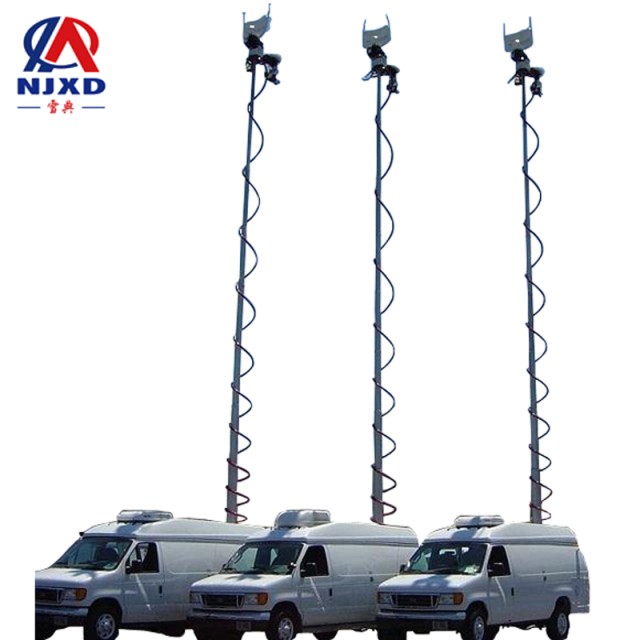
Working Principle of radio navigation system base station lifting antenna
Time:2021-06-24 View:
System working principle
The equipment or systems used in radio navigation include radio compass, voir navigation system, TACAN navigation system, Roland C navigation system, Omega navigation system, Doppler navigation system, satellite navigation system and the developing "navigation star" global positioning system, etc.
The radio signal contains four electrical parameters: amplitude, frequency, time and phase. During the propagation of radio waves, a certain parameter may change related to a certain navigation parameter. The corresponding navigation parameters can be obtained by measuring this electrical parameter. According to the different measured electrical parameters, radio navigation system can be divided into four types: amplitude type, frequency type, time type (pulse type) and phase type. According to the navigation parameters to be measured, the radio navigation system can also be divided into four types: angle measurement (azimuth angle or angular altitude), distance measurement, distance measurement difference and speed measurement. Hyundai is also divided into foundation (equipment is mainly installed on the ground or sea surface) and Air Base (equipment is mainly installed on flying planes) according to the main installation bases of radio navigation device. And satellite base (equipment is mainly installed on navigation satellites) 3 kinds. According to the action distance, it can be divided into four types: short range, long range, super long range and global positioning.
Radio navigation angle measuring system
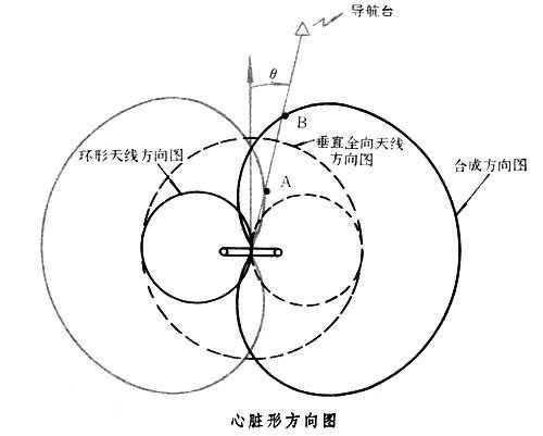
Using the characteristics of radio wave rectilinear propagation, turn the Circular directional antenna on the aircraft to the position where the amplitude of the received signal is the smallest, so as to measure the radio heading (see Radio compass), this belongs to the amplitude navigation system. Similarly, the azimuth angle of the ground navigation station relative to the aircraft can also be determined according to the different phases of the radio signals received at different positions of the aircraft by using the direction map of the rapid rotation of the ground navigation station (see vole navigation system), this belongs to the phase navigation system. The angle measuring system can be used for aircraft return (keeping certain navigation parameters unchanged, for example, keeping the radio heading zero and guiding the aircraft to navigation station). The trajectory of equal points of geometric parameters (angle, distance, etc.) is called position line. The position line of the angle measuring system is a straight line (the intersection line between the cone and the ground plane of the plane where the angle parameter remains constant). The intersection of the two straight line position lines can be obtained by measuring the heading of the two stations, which is the position of the aircraft.
Radio navigation ranging system
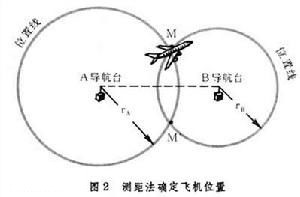
Take advantage of the constant speed rectilinear propagation of radio waves. Install a set of receiver and transmitter on the aircraft and the ground navigation platform. The plane sends navigation station to the ground interrogating signal, and the ground navigation station receives and forwards the answer signal to the plane. The response signal received by the aircraft receiver lags behind interrogating signal. The distance between the plane and navigation station can be calculated by measuring the lag time. Using the reflection characteristics of radio waves, the distance can also be obtained by measuring the lag time of reflected signals from the ground navigation station or aircraft. The position line of the radio navigation ranging system is a circle, which is formed by the intersection between the position surface of the ball with navigation station equidistant ground and the center sphere with the height of the plane. The ranging system can guide the aircraft to wait for flight at the airport, or determine the position of the aircraft by the intersection of two circular position lines (Figure 2). The double value of positioning (with two intersections) can be eliminated by the third circular position line. The ranging system can be pulsed, phase or frequency.

Radio navigation distance difference system
Install a receiver on the plane and set 2 to 4 navigation station on the ground. Each navigation station transmits radio signals synchronously (time synchronization or phase synchronization), and the time lag of each signal reaching the receiver of the aircraft is proportional to the distance from navigation station to the aircraft. The distance difference can be obtained by measuring the time difference of their arrival. The trajectory of the point keeping equal distance difference with the two fixed points is spherical hyperboloid, so the position line of this system is a hyperbolic curve formed by the intersection of spherical hyperboloid and the geocentric sphere at the height of the aircraft. Two hyperbolic curves can be obtained by using 3 or 4 ground navigation station. According to the intersection of the two hyperbolic curves, the position of the aircraft can be determined (figure 3). The double value of the positioning can be eliminated by the third hyperbola. Most of the distance difference systems used in modern times are pulse or phase.
Radio navigation speed measurement system
Most of these systems work with Doppler effect. Doppler navigation radar installed on the plane transmits radio signals in centimeter band to the ground with narrow beam. Due to the Doppler effect, the frequency of the signal reflected by the ground received by the aircraft is different from that of the transmitted signal, and there is a Doppler shift, the velocity of the aircraft relative to the ground can be obtained by measuring Doppler frequency shift (see Doppler navigation system). By using the pitch angle and heading angle given by the vertical datum and heading datum on the aircraft, the radial velocity is decomposed into the eastward velocity and northward velocity, and the position of the aircraft at that time can be obtained by integrating the time respectively. The position line of Doppler velocity measurement system is also hyperbolic, which is formed by the intersection between the cone with equal Doppler frequency shift and the geocentric sphere with the height of the aircraft. Doppler navigation velocity measurement system belongs to frequency type (see aircraft navigation system).
China's radio navigation system
There are two main types that are currently being used in our country. One is called non-directional beacon, also called Medium Wave navigation station, abbreviated as NDB; The other is a system composed of very high frequency omnidirectional Beacon (abbreviated as VOR) and range finder (abbreviated as DME).
In the medium wave navigation station system, the aircraft uses a rotatable loop antenna to receive signals. When the direction of the strongest radio wave is detected, the antenna stops rotating, so the orientation between the radio station and the aircraft is measured. If the plane flies in this direction, it can accurately fly to the position where the radio station is located. Zhongbo navigation station has low accuracy and is easily affected by the weather, but its price is cheap and its equipment is strong and durable, so many small and medium-sized airports in the world and most airports in developing countries still use it. Airports in the vast western regions of our country are also using this system.
The very high frequency omnidirectional beacon uses very high frequency radio waves, rectilinear propagation, which are not affected by the weather and have high accuracy. The antenna of VOR rotates continuously when transmitting, and the emitted signal changes according to the direction. When the aircraft receives the VOR signal, the instrument on the aircraft automatically indicates the north direction and the direction of the aircraft relative to the launch pad according to the frequency and intensity changes of the signal. The effective range of VOR is within 200km. Usually, a VOR station is established every 150 kilometers on the route. According to the position of the VOR station marked on the aviation map, the plane can fly smoothly on the route. When flying on the VOR route, the driver can only know the direction of the launch pad, but cannot determine the distance between the aircraft and the launch pad. When the rangefinder system is used together with VOR, this problem is solved. The ground launch platform and the VOR platform of the DMS are built in the same place or near the airport. The frequency it uses is ultra-high frequency, and the frequency is about 1000 MHz. This system consists of the interrogator on the plane and the answering machine on the ground station. The interrogator on the plane sends a pair of pulse signals to the ground. The interval between these pulses is random, which makes the signals sent by different planes different. The ground transponder receives this pair of pulse signals and sends back the same pair of pulse signals. The distance between the plane and the ground station can be calculated by multiplying the time consumed by sending out the signal and receiving the return signal with the speed of radio wave propagation. The distance that the rangefinder can measure can reach up to 500 kilometers, and the error is only about 200 meters. Each plane flying in the sky has different intervals of pulse pairs during inquiry, and only receives its own pulse signals when receiving them. At the same time, when several planes ask the ground station, their signals will not be confused with each other. The radio waves of the VOR--DME system draw a clear channel in the sky, which is called the air route. When the plane flies on the road, it can know its course and position from the instrument at any time. According to the scheduling of the ground controller, it flies one by one according to the waypoint and has been flying all the way. VOR--DME navigation system ensures that the aircraft can fly safely and orderly, greatly improving the air traffic flow and flight safety. Now this system has become the main navigation method in most parts of the world.
The cost of building a VoR-DME route is very high. It is impossible to build air routes between all stations on the ground. Generally, air routes can only be set up between central cities or between central cities and General cities. If the plane flies between two ordinary cities without air routes, in order to ensure flight safety, the plane has to take a flight from one city to the central city along the existing air routes, then follow another route to the general city you are going. This flight not only wastes fuel and time, but also makes the route crowded. This problem was solved only after the electronic computer was applied on the plane. The signals received from more than two VOR ground stations are processed by computers on the plane to obtain a route that actually has no ground stations, and an imaginary route point is set on this route, the plane flies according to this route and can also reach its destination smoothly. This specially designed computer is called airline computer. After the plane is equipped with such a computer, it can fly according to the route calculated by the computer at the place where it can receive signals from more than two VOR ground stations. This method is called regional navigation. It expands the navigation range of VOR from several routes to a plane, which is the whole plane that the radio signals of each VOR navigation station can cover.
The very high frequency and ultra high frequency radio waves used in the VOR--DME system are rectilinear propagation, and the operating distance is within 200 kilometers. In the vast ocean or a large area of no man's land, it is impossible to build many VOR stations connecting a route. In order to meet the needs of long-distance navigation, Roland System and Omega system are also developed. These two systems use radio waves of low frequency and very low frequency, and the operating distance is more than 2500 kilometers. As long as few such stations are set up on the surface of the Earth, the aircraft can fly over the ocean or the vast No Man's Land to navigate. The disadvantage of this kind of navigation is that the accuracy is not high enough, and it needs a transmitting station with very powerful power. After 1960 s, relevant professionals began to look for better ways to replace the radio navigation system.
Beidou navigation system
Beidou satellite navigation system officially entered the International Maritime Organization global radio navigation system.
On November 17-21, the 94th meeting of the Maritime Safety Committee of the International Maritime Organization was held in London, England. The Ministry of Transport organized a delegation to attend the meeting, on behalf of the Chinese government, it also promised to the International Maritime Organization the service performance, operation and maintenance management requirements of Beidou satellite navigation system in China, as well as the application policies of Beidou satellite navigation system in the international maritime field, it expresses the responsibility and attitude of our government.
The relevant person in charge of the Ministry of Transport pointed out that as A Class A member of the International Maritime Organization, the recognition of Beidou satellite navigation system by the International Maritime Organization will drive the internationalization of Beidou satellite navigation system in the navigation field, industrialization. Beidou satellite navigation system has also officially become an integral part of the global radio navigation system and has obtained the international legal status for maritime applications. This is also the first time that China's Beidou satellite navigation system standard has been systematically recognized by international organizations.
After the approval of the International Maritime Organization, our country will continue to comprehensively promote the standards, specifications, standards and regulations of international technical organizations such as the International Electrotechnical Commission, the International Navigation Mark organization, the International Maritime Radio Technical Commission, and the International Telecommunication Union, the formulation and revision of guide documents to realize the further all-round application of Beidou system in the field of international maritime affairs.
CATEGORY
NEWS
- Base station emergency communication radio navigation system
- Working Principle of radio navigation system base station lifting antenna
- Application and analysis of lifting monitoring in digital oilfield
- Importance of Application survey of lifting monitoring equipment
- Fore-end of lifting security monitoring