NEWS
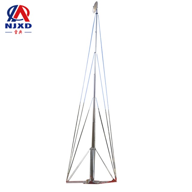
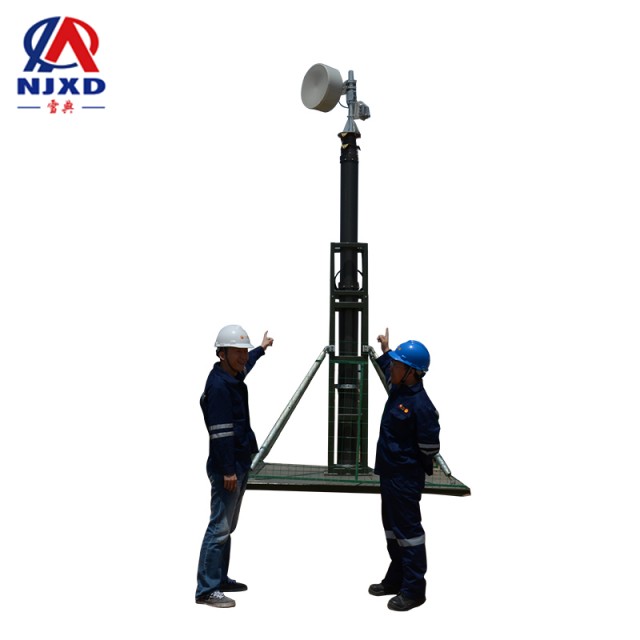
Antenna feed wire lifting antenna bracket equipment
Time:2021-07-27 View:

Antenna feeder refers to the electrical signal energy transmission line between connecting antenna and transceiver. Common feeders include overhead open wire, coaxial cable, waveguide, etc.
Definition
Antenna feeder refers to the electrical signal energy transmission line between connecting antenna and transceiver.
Classification
Common feeders include overhead open wire, coaxial cable, waveguide, etc.
2.1 Overhead open line
Overhead open line is the most commonly used feeder of line antenna is overhead double line transmission line. Its advantages are simple structure, economy and small loss. Its disadvantages are that antenna effect is easily generated when the frequency is high. Therefore, it is mostly used for long, medium, short wave, or ultra short wave band with small transmission distance. In order to overcome the disadvantage of antenna effect, shielded double wires can also be used as feed lines. Using Dielectric insulated double wires in low power transmission can not only be affected by external climate changes, but also have the advantages of convenient installation and low price. The overhead four-wire or six-wire transmission line adopted by the transmitting station or receiving station is the deformation of the two-wire transmission line. As the cross section of the wire increases, the transmission loss decreases accordingly. Receive diagonal interconnection of four-wire transmission lines can reduce spatial interconnection and avoid interference.
2.2 coaxial cable
When the frequency increases, coaxial cable can overcome the antenna effect of transmission line. Coaxial cable consists of an inner conductor and coaxial external conductor. The source voltage is connected to the inner conductor and the external conductor respectively. External conductor generally should be grounded, with shielding effect. Coaxial line is an asymmetric feeder. When connecting to a symmetric antenna, a corresponding converter should be added. The inner conductor of coaxial cable is generally copper wire, external conductor can be braiding thread, or copper and aluminum make coil tube, and the two are insulated with high frequency medium (such as polyethylene). It has filling, spacer, spiral belt, fish cell and other forms, and has the advantages of flexibility, convenient installation, uniform impedance and so on, so it is widely used in occasions with small transmission power. Hard coaxial line inner conductor is copper core, external conductor is copper tube, filled with dry compressed air or other inert gas (such as nitrogen), which can improve the ability to resist wear and moisture. The inner conductor is generally supported by washers or spiral belts. It is suitable for transmitting high power.
2.3 waveguide
When the frequency increases again, due to the skin effect, the loss of the inner conductor increases coaxial line; The power capacity decreases, so the inner conductor can be canceled and the hollow waveguide can be used to transmit energy. There are two kinds of commonly used feed waveguides: rectangular and circular. The electromagnetic wave propagating in the waveguide is no longer transverse electromagnetic wave (TEM wave for short), but transverse wave or transverse magnetic wave (TE or TM wave for short). Compared with coaxial feeder, waveguide has the advantages of small loss, large power capacity and simple manufacture. The disadvantage is that it is easy to generate unnecessary wave patterns (transmission modes) and is limited by Threshold frequency, the precision requirements of processing and installation are relatively high.

Main parameters of feeder
The main parameters of the feeder include characteristic impedance, standing wave ratio, transmission loss (or efficiency), breakdown voltage, power capacity, frequency span, etc.
Sometimes, in order to save money or be limited by the antenna site, two (or more) transmitters need to share a pair of antennas. At this time, feeder from each transmitter should be added with a filter before receiving the common antenna, so that the electromagnetic energy flow of the machine can pass smoothly, while the electromagnetic energy flow of other transmitters will not. Backflow. Enter the local machine. When designing the filter device, it is necessary to ensure that all transmitters can match the antenna when working separately.
The same receiving antenna can also be shared by two (or more) receivers. At this time, the radio waves received by the antenna are connected to each receiver through the broadband amplifier and the shunt coupling device (called antenna sharing device).
In addition, several transmitters (or receivers) can also be connected to several different antennas through switching switches on the switch. The requirements for these switches are simple device, convenient operation and small reflection.
Requirements for feeder
The requirements for the feeder mainly include the following aspects:
(1) In principle, the feed line should have no antenna effect: the feed line connecting the transmitter should not radiate electromagnetic energy; The feed line connecting the receiver should not be induced by the external electric field to pick up electromagnetic energy.
(2) The efficiency of transmitting electromagnetic energy by feeder should be as high as possible under reasonable conditions, that is, the loss on feeder (including transmission loss and reflection loss at each interface) should be as small as possible.
(3) the standing wave on the feed line should be as small as possible, that is, the characteristic impedance of the feed line should match the input impedance of the antenna. Avoid loss of transmission efficiency due to mismatch, excessive high voltage, Corona or breakdown, etc.
(4) the feeder should have sufficient frequency span and power capacity.
(5) When components need to be connected to coaxial or waveguide feeder lines, such as impedance converter, tuning device, power synthesizer (distributor), attenuator, phaser, filter, the switching switch and the same antenna are used as the duplexer added during transmitting and receiving at the same time, and the insertion loss and reflection loss should be reduced as much as possible.
With the development of radio technology, micro-strip transmission lines, surface wave transmission lines, dielectric waveguides and so on have appeared one after another.
CATEGORY
NEWS
- Feeder types lift rod built-in feeder
- Antenna feed wire lifting antenna bracket equipment
- Short wave communication system antenna lifting bracket
- Application of spread spectrum communication mobile communication ups and downs
- Brief introduction of microwave communication technology lifting microwave antenna bracket