NEWS
Feeder types lift rod built-in feeder
Time:2021-07-28 View:
Feeder, also known as cable, plays the role of transmitting signals in the cable TV system. Through it, the signals received by the antenna are transmitted to the front-end system, and the signals output by the front-end are also transmitted to the TV sets of various users by the cable. Therefore, the quality and model of feeder are important factors that directly affect the reception effect and signal transmission quality of cable TV system.
Basic Introduction
Feeder is a signal line connected to the early TV set and outdoor antenna. The flat shape is generally double wire, the line body is insulating plastic, there is no shielding layer outside, and the anti-interference ability is extremely poor. The performance of outdoor use will also be affected by rainy weather. Now, due to the popularity of cable TV, coaxial cable is completely replaced television signal wire.
Feeder includes the lower lead of the antenna and the trunk line, branch line, branch line, and subscriber line of the system. The feeder used in cable TV system mainly include flat feeder, coaxial electrical environment and optical cable. Coaxial cables are the most widely used.
Its main task is to effectively transmit signal energy and transmit the signal power from the transmitter to the input of the transmitting antenna with minimal loss, or transmit the signal received by the antenna to the receiver input with minimal loss, and at the same time, it does not generate stray interference signals, so the transmission line must be shielded. When the physical length of feeder is equal to or greater than the wavelength of the transmitted signal, the transmission line is also called a long line.

Feeder types
Flat feeder
Flat feeder is also called parallel feeder. It consists of two parallel wires, and the two wires are fixed with insulation material such as polyvinyl chloride or polyethylene. The feeder produced in our country mainly include SBVD and SBYD, the former is hard and the latter is soft, but the former has less loss than the latter. Because the two wires of parallel feeder have equal capacitance to ground, they are also called balanced or symmetrical feeder.
The diameter of the parallel feeder wire is between 1mm and several mm, and the distance between the two wires is no more than 1/10 of the wavelength of the transmitted signal, generally about 13mm. The characteristic impedance of parallel feeder is 300Ω, and the anti-interference ability is poor, but the price is cheap. Parallel feeder has a large loss on the transmission signal, so in the cable TV system, the connecting line segment and part of the subscriber line between components adopt flat feeder.
Coaxial cable
Coaxial cable coaxial cable has small loss and strong anti-interference. The characteristic impedance of common coaxial cable is 75Ω and 50Ω. In urban cable TV, coaxial cable is directly connected with signal source and TV, it is an ideal TV signal transmission line. Common coaxial cables consist of inner conductor, insulating layer, shielding layer and outer protective layer.
The inner conductor mainly plays the role of signal conduction in the cable, and the solid copper conductor is often used. Large-diameter cable in order to increase the mechanical strength, copper-clad steel is also used as the inner conductor.
The shielding layer is made of copper wire braiding, which plays a dual role of conductive and shielding. When using, the metal shielding end should be grounded.
The insulator is located between the inner conductor and the metal shielding layer, and requires the use of insulation medium with low high frequency loss to make a structure similar to lotus root core. Since the supporting effect of insulator makes the conductor concentric with the shielding layer, it is called coaxial cable.
The outer protective layer is made of rubber, polyethylene and other materials, wrapped outside the shielding layer, and has the functions of mechanical protection, sealing, moisture prevention, corrosion prevention and so on.
Technical parameters
Characteristic impedance
In the cable TV system, all components connected with cables must achieve impedance matching. Therefore, the characteristic impedance of coaxial cable is an important technical parameter to be considered during system design and installation. The characteristic impedance of coaxial cable is related to the diameter d of inner conductor, inner diameter D of metal shielding layer and dielectric constant ε of insulation material, which can be calculated by the following formula:
Characteristic impedance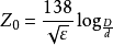
From the formula, it can be seen that the characteristic impedance of coaxial cable is determined by the diameter of conductor and the medium between conductors, and has nothing to do with the length of cable.
Attenuation Characteristics
Attenuation characteristic refers to the loss when coaxial cable transmits TV signals. The transmission line of cable TV system usually adopts coaxial cable with impedance of 75Ω. The transmission of TV signal in cable should produce attenuation. The attenuation is related to the diameter of cable conductor, cable length, the dielectric material is related to the frequency of the transmitted signal. The larger the diameter of the cable conductor and the lower the frequency of transmitting signals, the smaller the attenuation. On the contrary, the greater the attenuation. Therefore, the transmission of TV signals in cables will produce the following two situations, namely, the transmission of signals with the same frequency in cables of the same type and length, even if the cable length is equal, the attenuation of signal level is different; signals of different frequencies are transmitted in cables of the same type and length, and the attenuation is also different.
Temperature characteristics
The attenuation of cable will increase with the increase of temperature, which is called the temperature characteristic of cable. The temperature coefficient of general cables is 0.2%dB/℃, that is, when the temperature rises by 1℃, the attenuation of cables increases by 0.2% on the original attenuation. Temperature compensation is required for long-distance signal transmission.
Return loss
Return loss is the increase of reflection wave and attenuation due to the uneven impedance of the cable, which has a great influence on the definition of the image. The causes of return loss include the quality problems of the cable itself, which are also related to improper use and maintenance, mainly including:
(1) the structural dimension of the cable produces deviation or material deformation during the production process;
(2) during installation, the cable is bent to a right angle or crushed at the corner, causing structural deformation;
(3) the cable deteriorates due to moisture, high temperature and other factors, causing characteristic impedance changes.

Antenna feeder matching
In the cable TV system, the connection between components and components, components and feeder must achieve impedance matching, otherwise, high-frequency signals will be reflected during transmission in the feeder, on the one hand, this increases the energy loss of the signal in the transmission process; On the other hand, this reflected wave will affect the transmission quality of the signal, resulting in image ghosting when users watch it. Therefore, impedance matching is an important issue in the design, installation and use of cable TV system.
Generally, the antenna and Feeder are matched and connected, which means that the connection between the two has the following three conditions:
(1) the impedance of the antenna is pure resistance (that is, the reactance is 0), which enables the lower lead of the antenna to obtain as much energy as possible from the antenna and improves the signal transmission efficiency.
(2) the impedance of the antenna feed end should be equal to the characteristic impedance of feeder. When the two are different, the transformation of different impedances can be realized by impedance converter or other methods.
(3) the feed terminal of the antenna is balanced output. If parallel feeder is used as the lower lead of the antenna and the impedance of the two is the same, it can be directly connected in this case. If a coaxial cable with an impedance of 75Ω is used as the lower lead, balance-unbalance conversion is also required.
System Maintenance
The maintenance of cable and antenna system should focus on spring inspection and autumn inspection. The main feed tube, Rheostat and feeder cable should be checked carefully and comprehensively. Feed head and jump splicing connection and sealing of each part. Daily maintenance can observe the standing wave ratio indicated on the output power meter of the TV transmitter (normal is S<1.1), and the maintenance work on the tower can start with the fixing of the main feed and sub-feed cables, splicing should be used for fixed jump copper screws, and the jump splicing should be in good contact with the feed head. For rheostat, the sealing of each connection part and feed cable head should be carefully checked, every summer, check to prevent water from entering, and find out the cause and deal with the problem in time.