NEWS
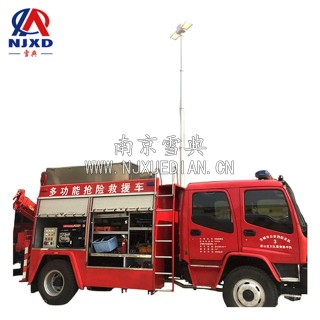
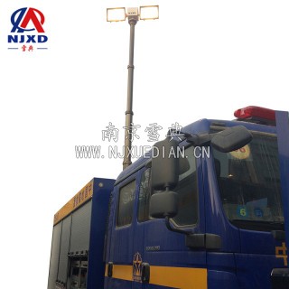
Work current of lifting lighting lamps
Time:2021-02-22 View:
Maximum Work current
The maximum work Current refers to the maximum current Imax of the installed strain gauges allowed to pass through the sensitive gate without affecting its operating characteristics. Work current large, the output signal is also large, the higher the sensitivity. However, if the work current is too large, the strain gauges will be overheated, the sensitivity coefficient will change, the null drift and creep will increase, and even burn strain gauges. The selection of work current should be determined according to the thermal conductivity of the test piece and the shape and size of the sensitive grid. Usually, about 25mA is taken during static measurement.
75mA to 100mA is recommended for dynamic measurement or foil strain gage. Foil strain gage the heat dissipation condition is good, and the current can be larger. When measuring materials with poor thermal conductivity such as plastics, glass and ceramics, the current can be smaller. The maximum work current is related to factors such as strain gauges itself, test piece, adhesive and environment.
Static work Current
Static work Current refers to the current in no signal state or standby state, such as the current in the radio without radio signal state. Dynamic work Current refers to the current in the signal state, such as the current in the radio receiving the radio signal.

Static current
What is static current? When there is no signal input, the current flowing through the triode usually refers to the current flowing through the emitter.
Static current is certainly a waste, but the problem is that triode is not an ideal component. If you are reluctant to pay for this paving cost, it will not only lead to switch distortion, moreover, the amplification factor of triode is relatively stable under a certain current, or the linearity is relatively good.
Static current is zero
If the static current is zero, the motherboard has not received external instructions or the static current loop has an open circuit. The external instructions mentioned here are 19V of the main power supply of the motherboard (some mainboards are 16V), if it has not been transmitted to the motherboard, it is necessary to see if the transmission path of 19V voltage supplied to the motherboard has been disconnected (OPEN). In many cases, there is a problem with the 19v transmission path. 19V is supplied to the main power chip SC1404 on the main board through a large inductor PL7 through the power interface to the main board. Also, is the inductance PL8 and PL6 on the circuit that generates 3V_AUX and 5V_AUX OPEN? Why is this phenomenon also caused here, because there must be a circuit with current, this is a static loop. If this circuit is disconnected, there will be no static current. Let's mention it first. This principle is also a judgment basis to solve the problem of large static current.

Small static current
The small static current means that the three original voltages do not come out. However, as long as there is a current, it means that the external command to the motherboard has been sent to the SC1404 main power chip. Then why is the static current small? That is because SC1404 has not worked yet, some people think that SC1404 is broken when they think of this step, and then they start to change SC1404, but there are few changed ones. What if it is not good? There is no way out. Here, I would like to remind you that the mainboard should not change parts easily, because the part you want to change before you are sure is just a suspect. The following maintenance idea is that SC1404 does not work, then it must have conditions when working. Let's see what the working conditions of CS1404 are. First, SC1404 must have an external instruction 19V voltage, there is also a VL signal measured with a multimeter voltage range of 5V. There is also an aux_off# signal, which indicates that the high level is effective and the measurement is 5V with a multimeter. If this signal is locked, SC1404 will not work. Basically, these signals are controlled. There are also SC1404's 23th foot and 22th foot, which are high potential (hpot) nearly 19v. If you find that the VL or aux_off# signal is abnormal, follow this signal to find it. You may not know it very well here, however, this chip SC1404 and MAX1632 used on some notebook motherboards basically work as a working principle.