NEWS
Antenna telescopic bracket antenna pattern
Time:2021-07-06 View:
It is also called radiation pattern and far-field pattern (far-field pattern).
The so-called antenna pattern refers to the pattern that the relative field strength (normalized modulus) of the radiation field changes with the direction at a certain distance from the antenna, it is usually represented by two mutually perpendicular plane patterns in the maximum radiation direction of the antenna.
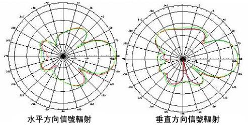
Antenna pattern can be divided into horizontal plane pattern and vertical plane pattern.
Definition
The so-called antenna pattern refers to the pattern that the relative field strength (normalized modulus) of the radiation field changes with the direction at a certain distance from the antenna, it is usually represented by two mutually perpendicular plane patterns in the maximum radiation direction of the antenna.
Antenna pattern is an important figure to measure antenna performance, and various parameters of the antenna can be observed from the antenna direction map.
The antenna pattern is used to indicate the directivity of the antenna. The so-called "antenna directivity" refers to the relationship between the relative value of the antenna radiation field and the spatial direction under the condition of the same distance R in the far region.
Classification
1. The line antenna erected on the ground generally uses two mutually perpendicular planes to represent its direction map, namely: Horizontal plane direction map and vertical plane direction map.
2. Ultrahigh frequency antenna is usually represented by two planes parallel to the field vector, namely E-plane directional diagram and H-plane directional diagram.
3. According to the selection of coordinates, it can be divided into: rectangular coordinate direction map, polar coordinate direction map, three-dimensional direction map, etc.

Characteristic parameters
In order to compare the pattern characteristics of various antennas conveniently, it is necessary to specify some characteristic parameters. Mainly includes: main lobe width, side lobe level, front-to-back ratio, direction coefficient, etc.
1. Main lobe width: a physical quantity that measures the sharpness of the maximum radiation area of the antenna. Usually take the width between two half-power point of the main lobe of the antenna pattern.
2. Side lobe level: refers to the level of the first side lobe closest to the main lobe and with the highest level, generally expressed in decibels.
3. Front-to-back ratio: refers to the ratio of the maximum radiation direction (forward) level to its opposite direction (backward) level, usually in decibels.
4. Directional coefficient: At a certain distance from the antenna, the ratio of the radiation power flow density of the antenna in the maximum radiation direction to the radiation power flow density of the ideal non-directional antenna with the same radiation power at the same distance.
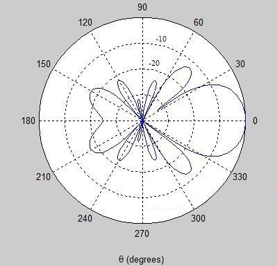
The radiation electromagnetic field of the antenna is distributed with the spatial angle (including azimuth angle and pitch angle) on the spherical surface with the antenna as the center and a certain distance as the radius, which is called radiation pattern, which is called radiation pattern for short. The radius of the sphere, that is, the distance from the field point to the antenna, must meet the far zone conditions.
Because the antenna pattern is generally petal-shaped, it is also called lobe diagram. The beam within the first zero radiation direction line on both sides of the maximum radiation direction is called the main lobe, and the beam opposite to the main lobe is called the back lobe, the beam between the other zero radiation directions is called sidelobes or sidelobes.