NEWS
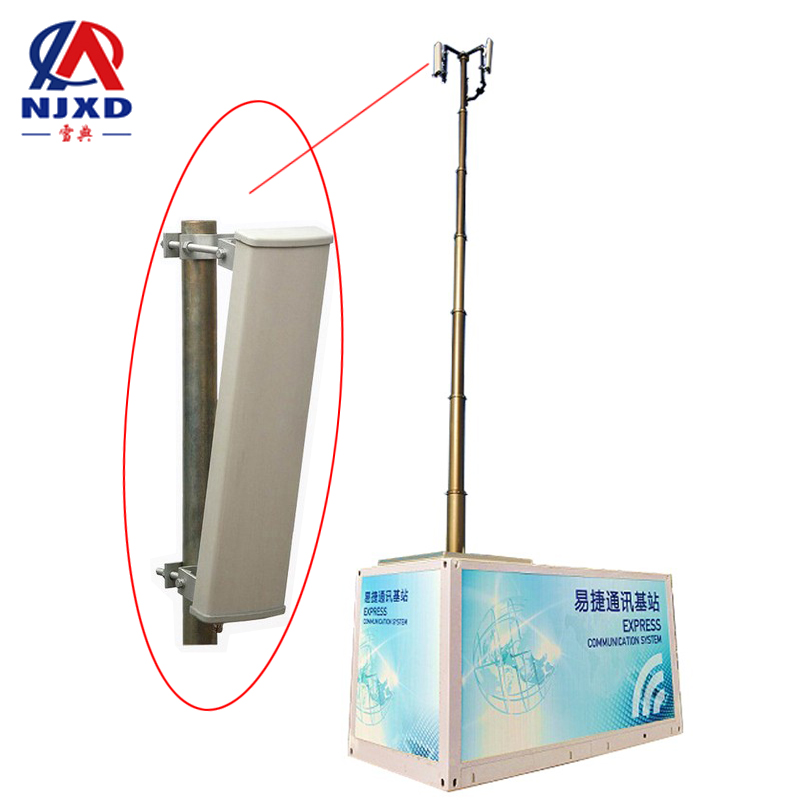
Lifting mast communication antenna directivity
Time:2021-07-07 View:

Antenna directivity refers to the electromagnetic field strength radiated by the antenna in different planes. The main expression method is the antenna's directivity, which is the main research direction of the antenna.
The characteristics of the antenna include impedance characteristics, directional characteristics, polarization characteristics and bandwidth characteristics.
The directivity of the antenna is described by the antenna pattern and half power beam width, the first zero beam width and the side lobe level.

Orientation concept
All radio equipments work on electromagnetic waves transmitted in space, and the transmission or reception of electromagnetic waves must be realized through antennas. According to IEEE standards, an antenna is defined as a "device that radiates or receives radio waves", that is, an antenna is such a component: effectively convert the high-frequency oscillating current in the circuit or the traveling wave on the feeder into some polarized space electromagnetic wave, and ensure that the electromagnetic wave propagates in the required direction (emission State), or effectively convert some polarized electromagnetic waves from a specific direction of space into high-frequency oscillating waves in the circuit or traveling waves on feeder (receiving state). The so-called wave polarization refers to the way that the electric field intensity vector E changes with time in the plane perpendicular to the propagation direction, that is, the orientation of the electric field vector in space. The above definition shows that the antenna has the following characteristics:
Impedance characteristics
The antenna should be able to convert high frequency current energy into electromagnetic wave energy as much as possible, which first requires the antenna to be a good "electromagnetic open system", and secondly requires the antenna and transmitter (source) match or match with receiver (load).
Directional characteristics
The antenna should make the electromagnetic wave concentrate in the required direction as much as possible, or have the maximum reception of the incoming wave in the required direction.
Polarization characteristics
The antenna shall be capable of transmitting or receiving electromagnetic waves of specified polarization.
Bandwidth characteristics
The antenna should have sufficient operating frequency band.
Principle
All kinds of radio equipments have different requirements on antenna directivity. For example, precision measurement radar requires that the electromagnetic waves radiated by the antenna are concentrated in a very small space solid angle, which is called "needle beam"; the communication base station and the television transmitting station require the electromagnetic wave to radiate evenly in the horizontal plane, that is, it has "omnidirectional", and usually uses the direction map and some related parameters to describe different directions.

Directional graph
The electromagnetic field radiated by the antenna is distributed with the spatial angle (including azimuth angle and pitch angle) on the sphere with the antenna as the center and a certain distance as the radius, which is called the radiation pattern. The radius of the sphere, that is, the distance from the field point to the antenna, must meet the far zone conditions.
Because the antenna pattern is generally a petal pattern. The beam within the first zero radiation direction line on both sides of the maximum radiation direction is called the main lobe, the beam opposite to the main lobe is called the back lobe, and the beam between the other zero radiation directions is called the side lobe or side lobe.
The three-dimensional pattern of the antenna is relatively vivid, and the radiation distribution of the antenna in the whole space can be clear at a glance, but the drawing is difficult.
In general, it is not necessary to carefully study every direction of space, therefore, in the design and test of the antenna, only two-dimensional directional patterns on two main planes are often used to characterize the radiation of the antenna in the whole space, the main plane generally refers to two special planes perpendicular to each other through the symmetry axis or the maximum radiation direction of the antenna, and the selection method varies depending on the specific antenna.
For example, for most antennas, the most common one is to take the E plane parallel to the electric field vector and the H plane perpendicular to the electric field vector.
Half power beam width, first zero beam width
It is sometimes not convenient to describe the directivity of the antenna by using the directional pattern, so the half power beam width, the first zero beam width and the secondary lobe electrical equality parameters are often used to represent the spatial distribution of the electromagnetic field energy radiated by the antenna.
Half-power beam width (also called lobe width) refers to the angle between two directions in which the power density in the main lobe of the pattern is equal to half of the maximum power density (or the field strength is 0.707 times the maximum).
The width of the first zero beam (also known as the opening angle of the main lobe) refers to the included angle between the first zero on both sides of the main lobe.
The level of the side lobe refers to the ratio of the maximum value of the side lobe to the maximum value of the main lobe, which is usually expressed by the split shell.
