NEWS
Product Introduction of lifting bracket wind resistance calculation of mast
Time:2020-06-29 View:
Product Introduction of lift rod
Lifting rod is a lifting rod device provided by professional mobile lighting equipment, communication, vehicles, monitoring, etc. It is widely used in various fields such as public security, fire protection, communication, meteorology, municipal construction, various natural disasters, on-site night rescue and rescue of Emergency Events; It can be installed in satellite news interview vehicles, relay vehicles, military, public security command vehicles, emergency communication vehicles, other special vehicles and other types of vehicles; They can also be used as the carrier of illumination in the sports field.
When the client equipment chooses the lifting rod, the original height, the maximum rising height and the maximum load of the pneumatic lifting mast should be determined according to the height from the mounting surface to the top of different types. It is convenient for the company to carry out personalized customization according to the needs of customers and cater to the solutions of customers;
When the lifting rod product is installed on the top, its original height is the shortest, which ensures the maximum height passing of the car body and reduces the wind resistance of the equipment as much as possible.
Technical setting of lifting rod
1. Height: the height of the lifting rod can be realized within 1-35 meters, and the height after being folded can also be designed according to the requirements of customers;
2. Load: the maximum load can reach 350 kilograms. If tower is adopted, the maximum load can exceed 800kg;
3. Wind resistance: the original resistance of non-pulling line is 6-level wind power, and the state of pulling line can resist 8-level wind power.
4. Torsion degree: Pneumatic lifting rod adopts anti-rotating reinforcement, which can effectively solve the problem of large torsion, only ≤±0.5 °;
5. Positive and negative deflection: due to the RS between joints of pneumatic lift rods, it is the lowest positive and negative deflection among all kinds of lift rods at present, only ≤±0.3 °. If tower is adopted, ≤±0.1 ° can be realized
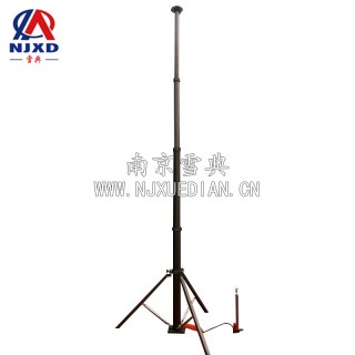
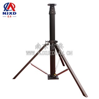
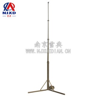
Installation method of lifting rod
1. Fixed mode: install the lifting rod on the top or surrounding of the equipment, and vertically lift the lamp equipment, camera equipment, antenna equipment and so on to the high altitude to realize the lifting equipment of the customer's predetermined function.
2. Moving mode: it can be realized by reinforcing the triangular bracket at the bottom. It can be moved up and down by opening the chassis of the triangular bracket and lifting the rod manually or automatically during operation.
3. Vehicle mode: the lift rod is fixed by opening holes in the car roof, or installed around the car, and fixed by the mop and support frame.
Material description
The lifting rod adopts high-strength 6063 aluminum alloy profile, and the surface is subjected to anodic hardening treatment, which has higher hardness, film thickness, abrasion resistance and corrosion resistance.
In addition, our company first realized the built-in pneumatic lift rod inside of the power line, which is a leading technology in China and further in beauty and performance
2. Wind resistance calculation
2.1 coefficient of bending section
Since the bottom of the top pipe is the weakest part of the mast, and the bearing bending moment is also relatively large, as long as the 202mm OD pipe can ensure normal use, the whole mast can be guaranteed to use.
202mm od bending section coefficient
w=πd2/32 ﹛1-﹙do/d ﹚4﹜=3.14×2022/32 ﹛1-﹙190/202 ﹚4﹜=181332mm2
2.2 gust coefficient
The so-called gust coefficient Kg is the ratio between the maximum instantaneous wind speed V2 and the average wind speed V2 in the observation time. It depends on the observation time, the average wind speed, terrain, ground roughness, the return period of the benchmark wind speed is related to other factors. Generally, Kg is between 1.2 and 1.5, and Kg = 1.3 is taken here.
V2=▽Kg=28×1.3=36.4m/s
2.3 Reynolds number of different diameter sections of lifting rod
2.3.1 Reynolds number
R2=V2d/V= 36.4×0.202/0.15×10﹣4=4.9×103
V-air motion viscosity coefficient, 0.15 × 10⁻⁴m 2/s
d-pipe diameter
2.3.2
The resistance coefficient CD of the lifting rod is determined by the changing range of Reynolds number of each section of the lifting rod.
Because the slenderness ratio of the lifting rod is relatively large and its surface is very smooth, we can regard the lifting rod as a smooth two-dimensional rod. The following figure shows the relationship curve between the resistance coefficient CD of the smooth two-dimensional cylinder and the Reynolds number Re.
It can be seen from the curve that the Re range of the lifting rod is just in the area where CD = 1.2.
2.4 The wind resistance at the top of the lifting rod top
D=CD·2/2PV22dlKg2
= 1.2 × 2/20 × 36.42 × 0.202 × 1.7 × 1.32
=57.67kg
2.5 strength check
σmax=Mmax/W=37.4×20×27×2000/20222=5.4Mpa
Σ = 205Mpa under 6063-T6. To ensure safety, σ = 160Mpa
Because σ max<σ, the mast can withstand the wind speed of 100 km/h. Under the condition of mechanical self-locking structure, the wind power the mast bears can multiply and withstand the wind speed of 11 grades.
3. Methods to improve wind resistance of mast
In the case of using the existing specifications of the mast, to improve the wind resistance of the mast, the following methods can be adopted:
1) lift the mast according to the weather conditions. When the wind is strong, lower the mast. When the wind is small, raise the mast.
2) use wind-resistant fiber rope. The correct and timely use of the fiber rope can greatly improve the wind resistance of the mast. The usage of the fiber rope is shown in the figure.
Set the Windward area of the load object to 0.85m2, and set the fiber rope on the top mast. The wind resistance strength corresponding to different fiber rope angles is shown in the table.
Rope angle 0 ° 5 ° 10 ° 15 ° 20 ° 25 ° 30 ° 35 ° 40 ° 45 °
Wind resistance strength (m/s) 17.0 18.5 20.0 21.6 23.2 24.9 26.8 28.9 31.3 32
3) choose other specifications of the mast of our company.
Load performance of communication lift rod -- calculation method of mast load
Maintenance Performance -- maintenance method of mast height
The pneumatic lift Rod realizes the retractable movement by injecting and discharging compressed air into the cavity of the mast. The maintenance of its height is realized by preserving a certain amount of compressed gas in the cylinder block, which is called "pressure maintaining" for short ".
To maintain the pressure, it requires the mast to have good sealing performance and the air source input and output control valve to have good sealing performance. However, theoretically speaking, no matter how good the sealing performance is, the air will leak slowly, which is the so-called "micro leakage" phenomenon. Therefore, maintaining height and pressure maintaining is only a relative concept. If you need to maintain a certain height for a long time, you need to continuously replenish air, which can be achieved through control technology. If the pressure detection device is installed on the gas path, when the air pressure is lower than a certain value, the air pump will be started to replenish the air. In addition, another method can be adopted to maintain the height of the mast, namely "mechanical maintenance". See the self-locking mast section.
Pressure formula pressure formula
Calculation Formula of thrust in cylinder
F=1/4πd2P
F is the thrust (N) generated by gas
d is the diameter of mast piston (cm)
P is working pressure MPa

CATEGORY
NEWS
- Characteristics of the lifting bracket of the lodging type mobile lighting lamp
- Product Introduction of lifting bracket wind resistance calculation of mast
- System and technical parameters of vehicle-mounted antenna lifting equipment
- Technical requirements for pneumatic antenna lifting bracket
- The characteristics of wire rope and its production and application